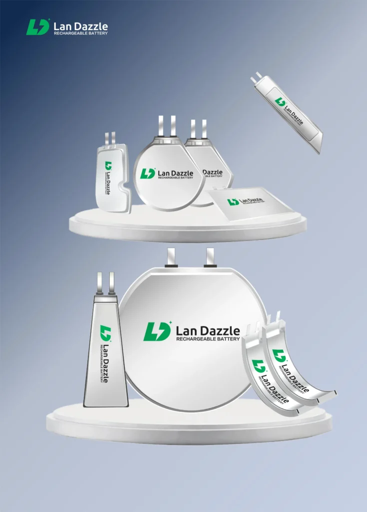
Battery internal resistance varies significantly among prismatic, pouch, and cylindrical cells because of differences in current paths, electrode structures, and tab designs. In general, for comparable cell designs, prismatic cells can achieve the lowest internal resistance, pouch cells are typically in the middle, while conventional cylindrical cells tend to have the highest, especially when single-tab winding designs are used.
Differences in Ohmic Internal Resistance: Current Path Determines the Baseline Level
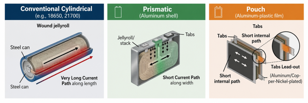
The ohmic internal resistance is largely determined by the cell’s structural design, particularly the current-collector conduction path and tab connection method.
Typical Ohmic Resistance:
Conventional Cylindrical > Pouch > Prismatic
Cylindrical Cells
- Typically use a single-tab or dual-tab winding design.
- The current-collector conduction path is relatively long, which increases the contribution of collector resistance.
- Small tab welding areas can result in relatively high contact resistance.
- Highest ohmic resistance among the three formats.
Prismatic Cells
- Generally use multi-tab winding or stacking designs.
- The current path is much shorter, minimizing the contribution of current-collector resistance.
- Large terminal cross-sectional areas enable large-area laser welding between the tabs and terminals.
- Lowest ohmic resistance among the three formats.
Pouch Cells
- Typically use a stacked electrode structure.
- The internal conduction path is short, resulting in relatively low internal resistance.
- However, the tabs are usually thin metal strips with limited cross-sectional area and relatively long lead-out lengths, increasing the resistance of the external current path.
- The ultrasonic welding area is relatively limited, resulting in higher contact resistance than the large-area laser-welded connections used in many prismatic cells.
- Intermediate ohmic resistance among the three formats.
Differences in Polarization Resistance
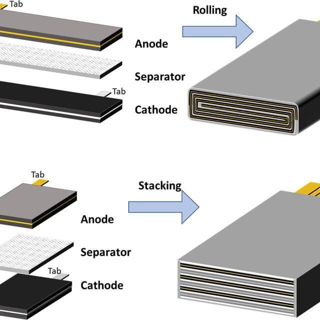
The difference in polarization resistance is mainly determined by the structural differences between winding and stacking. Among the three cell formats, pouch cells predominantly use a stacked structure, cylindrical cells mainly use a wound structure, while prismatic cells can use either structure.
Typical concentration-polarization resistance:
Pouch < Prismatic < Conventional Cylindrical
What Is Polarization Resistance?
Polarization resistance refers to the voltage loss that develops when a battery is under load due to electrochemical and mass-transfer limitations, rather than simple electronic resistance. It includes effects such as electrochemical reaction kinetics and lithium-ion concentration gradients, and becomes more pronounced as the discharge or charge current increases.
1. Pouch Cell Polarization Resistance
Pouch cells typically use a stacked electrode structure, with relatively thin individual electrode sheets and a large number of layers. This results in a short lithium-ion diffusion path through the electrode thickness, while electrolyte wetting is generally more uniform.
As a result, pouch cells tend to have the lowest concentration polarization, with polarization resistance increasing more slowly under high-current conditions.
2. Prismatic Cell Polarization Resistance
Prismatic cells often use a multi-tab winding structure, although stacked designs are also common. Compared with stacked pouch cells, the longer electrode path can lead to slightly less uniform ion distribution along the electrode length.
Therefore, concentration polarization is generally somewhat higher than in stacked pouch cells.
3. Cylindrical Cell Polarization Resistance
Conventional cylindrical cells typically use a single-tab winding structure, resulting in the longest electrode path among the three formats. The current and lithium-ion distribution can also be less uniform, creating larger local SOC gradients.
As a result, cylindrical cells generally exhibit the most significant concentration polarization, and their internal resistance can increase more rapidly as the C-rate rises.
Charge-Transfer Polarization Resistance
Charge-transfer resistance (Rct) refers to the resistance encountered when lithium ions undergo intercalation and deintercalation reactions at the electrode–electrolyte interface. It is an electrochemical component of internal resistance, and its intrinsic value is directly determined by the kinetics of the anode and cathode materials, electrolyte system, and properties of the SEI film.
The cell format itself—whether cylindrical, prismatic, or pouch—does not inherently change the intrinsic Rct of the materials. The differences mainly arise from structural design, including effective utilization of the active reaction area, uniformity of current-density distribution, and electrode–electrolyte interfacial contact conditions, which ultimately result in differences in the equivalent Rct of the complete cell.
Summary
Different cell formats can exhibit significant differences in both the composition and magnitude of internal resistance due to variations in structural design, current paths, and electrode configuration. However, there is no absolute winner—each cell format has its own advantages and can be optimized within its specific design architecture.
Our Stacked Battery Design: Lower Internal Resistance
Our batteries use a stacked electrode structure, which provides shorter and more uniform current and ion transport paths than conventional single-tab winding designs.
- Shorter current-collection paths reduce ohmic resistance and voltage loss.
- More uniform current distribution helps reduce local current-density concentration and polarization.
- Shorter lithium-ion diffusion paths help minimize concentration polarization under high-rate operation.
- As a result, our stacked cells can achieve low internal resistance, lower heat generation, and more stable power delivery.
This makes the design particularly suitable for smart rings, smart glasses, medical devices, AI wearables, and other compact high-performance electronics.
Looking for a low-resistance custom battery for your device? Contact LanDazzle to discuss your cell size, capacity, discharge requirements, and application needs.
Email: info@landazzle.com
Whatsapp: +8618938252128